APL series valve limit switch box is a kind of field instrument in the automatic control system to detect the valve state, to open or close the position of the valve to open and close (contact) signal output, is accepted by the program controller or computer search sampling, confirm the implementation of the next procedure. The product can also be used as an important valve interlock protection and remote alarm indication in the system.
APL series valve limit switch box detection of valve Angle displacement, through a coaxial connection or feedback drive shaft to generate rotation, so that the CAM touch the micro switch, so that the switch module contact closed or disconnected, through the terminal to the external switch signal, and through the indicator on the spot display. Must open the cover after power off. The outer diameter of the flameproof lead-in cable sheath is Ø7~8mm. Tighten the compression nut so that the inner diameter of the sealing ring holds the sheath of the cable tightly. Unused cable lead-in devices must be blocked. When installing, using and maintaining explosion-proof limit switches, users must comply with GB50058-92 "Code for Design of Electric Devices in Explosive Fire Danger Environment" and GB3836.15-2000 explosion-proof standard.
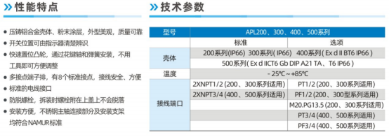
| APL-210N | APL-410N |
| Shell protection type(IP67) | Explosion-proof type(EXd Ⅱ BT4) |
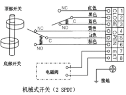
| Mechanical microswitch | |
| Voltage: Maximum AC 250V AC or DC DC | |
| EC:0.6A 125VDC,0.3A 250VDC,16A 1/2HP 125,250V AC 16(3)A 250V-T 105 | |
| Electrical interface G1/2″ | |
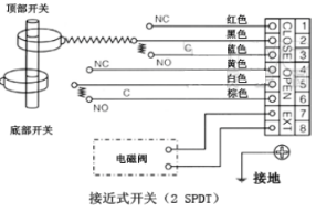
Option: Legend current output signal. Proximity switch, resistive potentiometer output signal.
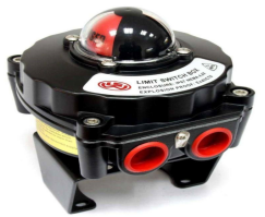

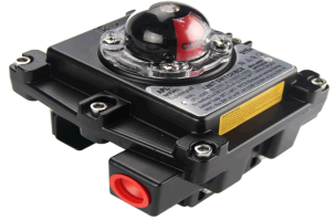
1.When the valve goes to the off position, adjust the red CAM so that the "off" switch has signal output.
2.The valve goes to the open position and adjusts the red CAM so that the "open" switch has signal output.
3.Let the valve go back and forth several times to make sure the limit switch signal is reliable.
APL series limit switches - Operation instructions
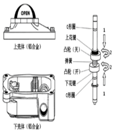
When the switch position needs to be adjusted, operate according to the arrow steps shown:
1、Push CAM spring compression, CAM out of spline engagement.
2、Rotate the CAM at will to adjust the required position, release the CAM after adjustment, and confirm that the CAM has been spring back to reset engagement.

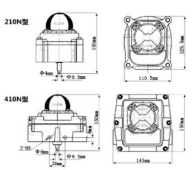

Notice to quotation: Optional accessories: solenoid valve, limit switch, two couplings
Please try to provide detailed parameters about each standard pneumatic ball valve, to facilitate our technical personnel for your accurate selection.