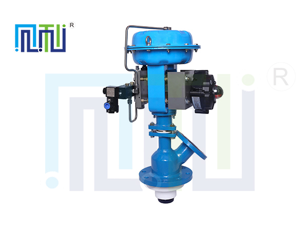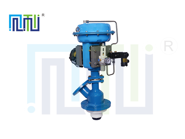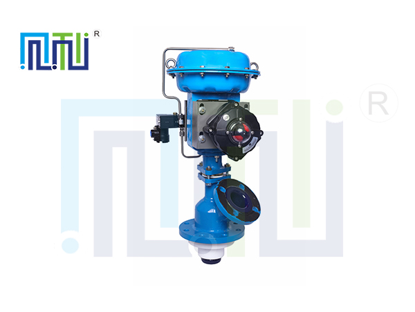
Pneumatic glass lined discharge valves are mainly used for the bottom discharge of reactors, tanks and other containers, connected to the bottom of the tank and other containers by means of the bottom flange of the valve. Glass lined discharge valve according to the needs of the actual situation, the bottom structure design is flat bottom type, the valve body is V type, reasonable structure design, to ensure that there is no residual liquid inside the valve body. The valve body cavity is equipped with erosion resistance, corrosion resistance of the sealing ring, in the opening of the valve moment, can protect the valve body from being washed by the medium, corrosion, and special treatment of the sealing ring, the surface hardness of HRC56-62, with high wear resistance, corrosion resistance function. Widely used in chemical industry, medicine, dyes, pesticides, organic synthesis, petroleum, food manufacturing and national defense industry and other industrial production and scientific research.
For all kinds of concentrations of inorganic acid, organic acid, organic solvent and weak alkali medium are strong rot resistance. However, it is not applicable to strong alkali, hydrofluoric acid and fluoride ionic medium, and phosphoric acid whose temperature is greater than 180℃ and concentration is greater than 30%.
Fourth, product parameters:
| Main parts | Valve body | Carbon steel lined with glass lining |
| gland | WCB | |
| disc | Carbon steel lined with glass lining | |
| packing | V - shaped PTFE, EPDM rubber ring, fluorine rubber ring | |
| Sealing ring | ||
| Applicable condition | Applicable medium | Water, steam, oil, nitric acid, acetic acid, hydrochloric acid and other corrosive media |
| Applicable temperature | - 10- 190℃ | |
| Manufacturing standard | YG-HG5- 15-79 、YG-HG5- 16-79 | |
| Flange size | GB/T9113 | |
| stroke | 25- 150mm (Optional, not fixed) | |
| Applicable air pressure range | 0.2-0.6MPa (The recommended pressure is 0.4Mpa) | |


| specification | import PN0.6MPa | exit PN0.6MPa | import PN1.0MPa | exit PN1.0MPa | Structural height (with handwheel) | ||||||||
| Flange outside diameter | Center hole spacing | n- Φ | Flange outside diameter | Center hole spacing | n- Φ | Flange outside diameter | Center hole spacing | n- Φ | Flange outside diameter | Center hole spacing | n- Φ | ||
| 50/32 | 160 | 130 | 4-14 | 120 | 90 | 4-14 | 185 | 145 | 4-18 | 140 | 100 | 4-18 | ≈650 |
| 80/40 | 190 | 150 | 4-18 | 130 | 100 | 4-14 | 200 | 160 | 8-18 | 150 | 110 | 4-18 | ≈650 |
| 100/50 | 210 | 170 | 4-18 | 140 | 110 | 4-14 | 220 | 180 | 8-18 | 165 | 125 | 4-18 | ≈670 |
| 125/80 | 240 | 200 | 4-18 | 190 | 150 | 4-18 | 250 | 210 | 8-18 | 200 | 160 | 8-18 | ≈670 |
| 150/100 | 265 | 225 | 4-18 | 210 | 170 | 4-18 | 285 | 240 | 8-22 | 220 | 180 | 8-18 | ≈670 |
Note: The above size is for reference only, the specific size is based on physical objects.